OPERATIONAL AMPLIFIER BASICS
by Harry Lythall
by Harry Lythall

Introduction
The Operational Amplifier (Op-Amp) was developed many years ago for analogue computing. This was in the days when the output information from a calculation was readable with a simple voltmeter. Fortunately for us, the Op-Amp can be misused for a huge variety of functions. In this page I will attempt to show what the Op-Amp is and a few uses of it.
What IS An Op-Amp?
Basically, the Op-Amp is nothing more than a differential amplifier that amplifies the difference between two inputs. One input has a positive effect on the output signal, the other input has a negative effect on the output. The component circuit symbol is:
The theoretically perfect Op-Amp has an infinite voltage gain, an infinite bandwidth and infinite input impedances. In this way it just senses an input voltage level without actually interfering with that voltage in any way. The perfect Op-Amp also has a zero-Ohm output impedance. It may therefore be used to drive heavy (in electronic terms) circuits.

A Practical Op-Amp
The practical Op-Amp is far from perfect, but the more you pay then the better the Op-Amp you get. The circuits I will give you in this article can all be built and used using the LM741 Op-Amp. Here you can find the datasheets for operational amplifiers, and other circuits, if you want a little extra reading. These chips look something like this: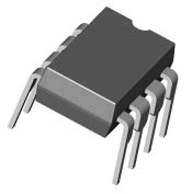
To understand a little more of what is inside the chip, here is a much simplified circuit diagram.
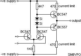
Now you have a little information about what the device is, let us take a look at what it can do.

Basic Function
The basic function of the Op-Amp is to multiply a voltage level by the gain of the amplifier. If you were to couple a DC level of +1v into the + input of our Op-Amp then the output would be 1v X 1000000 or one Million volts. The output, however, cannot exceed the supply voltage, so the output will be +20v DC.If you were to couple a DC level of +1v into the - input of our Op-Amp then the output would be -1v X 1000000 or MINUS one Million volts. The output, however, still cannot exceed the supply voltage, so the output will be -20v DC.
If you were to couple a DC level of +1v into both the - and + inputs of our Op-Amp then the output would be (-1v X 1000000) plus (1v X 1000000) = 0v.
In other words, both inputs act on the output simultaneously and the output is the sum of both input functions. If both inputs are identical then the output should always be zero. This is a good test for an Op-Amp. If you connected both inputs to the same input, then the output SHOULD be zero volts. In reality, there are small differences in the circuit's characteristics and components, this will result in a small "offset" voltage.
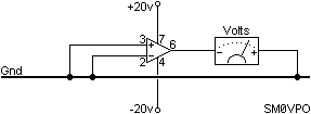
The offset voltage can be corrected on several Op-Amps by an internal circuits known as "offset null" which means that the offset voltage can be trimmed out.
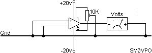

The Op-Amp As A Comparator - Logic
One of the most basic Op-Amp functions is the voltage comparator. Here the two inputs are used to compare two different voltages. If the input to the + input is greater than the input to the - input then the output will be 1000000 times the difference between the two inputs.Example, if the + input were +3.2vDC and the - input were +3.215vDC then the output voltage will be 1000000 X the difference between the two inputs, or 1000000 X -0.015vDC = -15000vDC. Again, the amplifier cannot output a voltage beyond the supply voltages so the output will become -20vDC.
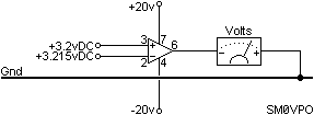
The basic voltage comparator can also have many other uses, for example, as a battery under/over voltage indicator.

The DC output from the 50K preset potentiometer will vary in sympathy with the 13.8vDC input to the whole circuit. The DC voltage across the Zener diode, however, will be a constant, quite independant on the input voltage. Assume the 50K preset is set to mid-position then the pot will deliver 13.8/2 = 6.9v to the Op-Amp + input. The Op-Amp will therefore always deliver a high voltage from it's output and the LED will be illuminated. If the input fell below 13.6vDC then the preset will deliver less than 6.8v to the Op-Amp and the Op-Amp output will change from High (13.8v) to Low (0v). A voltage warning indicator.
The Op-Amp comparator can also be used in many other applications where voltages vary, for example, the basic CR time-constant circuit. In this example, I have chosen to make a simple timer circuit.

Ok then, so now you know all about using the Op-Amp as a voltage comparator and some of the ways it could be used. It is probably time to start using the Op-Amp in some analogue circuits.

The Op-Amp As A Comparator - Analogue
The basic Op-Amp gain is for too high to be of much use in analogue circuits without some form of control. That form of control usually comes in the form of "negative feedback". This means simply connecting all, or a part, of the Op-Amp output back to the - input.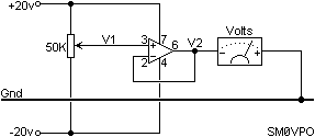
If you now vary the 50K potentiometer then the Op-Amp output will follow the input voltage from the pot. The advantage here is that any load placed on the Op-Amp will not affect the voltage since the Op-Amp controls it. Any error will be fed back in the opposite polarity and cause a correction. This circuit is a simple low current (20mA) variable voltage generator. You can increase the output current capability by adding a transistor for the Op-Amp to drive.

The power transistor will drop 0.7v between Base and Emitter (1.4v for a power Darlington transistor) which would otherwise lower the output voltage of the complete PSU. I have connected the - input of the Op-Amp, not to the Op-Amp output, but to the output of the regulator transistor. The circuit functions exactly as before, but the result of the 100% negative feedback will be to maintain the output of the transistor TR at the correct voltage. The output of the Op-Amp may be a volt or two higher than this; whatever is needed to control the transistor.
In reality, this circuit would be a little dangerous to use withou some form of current limiting, but that is outside the scope of this article. There are circuits elsewhere on my homepages.
One other small point, all devices generate noise. The Op-Amp is no exception, but in the above circuit the negative feedback will remove all traces of noise from the output of the PSU that are generated WITHIN THE FEEDBACK LOOP. The 50K pot and Zener diode lie outside the feedback loop. The 50K pot will not generate much noise, but the Zener diode is a very noisy device. It should be decoupled with a large electrolytic capacitor.
Another point here is temperature stability. A 15v zener diode will have a voltage variation of about 25mV for every degree Centegrade. A 10 degree rise in temp will therefore cause the full-voltage output from the PSU to vary by 1/4 of a volt! To overcome this we can modify the circuit to use the gain of the Op-Amp. We know that high-voltage Zener diodes have a +ve temperature coefficient and low-voltage Zeners have a -ve coefficient. A 5.6v Zener has a temperature coefficient of about 0v per degree centigrade. So let us substitute the 15v Zener with a 5.6v Zener. Now let us modify the circuit so we can still have a 0-15v variable PSU.

If the Zener generates 5.6v and the voltage pot is set to maximum, then the + input of the Op-Amp is +5.6v. This will drive the output of the Op-Amp high, until the - input of the Op-Amp (pin 2) is also 5.6v. Pin 2 is connected to the junction of R1 and R2 and this can only become 5.6v if the right-hand side of R1 is 15.6vDC. Our PSU now works and has a very good temperature stability.

Audio Amplifiers
The Op-Amp makes an ideal audio amplifier with very few external components. With an output current of up to 20mA then it can also drive headphones and even high-impedance speakers, eg. 50 - 80 ohms. To use the Op-Amp for linear (undistorted) audio applications we always need to use negative feedback. It is the negative feedback that "tames the wild beast". With an "open loop" voltage gain of over 1000000 times then we do need to "tame" the amplifier.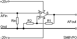
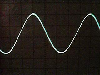
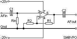
This amplifier would be quite fine if you had both + and - 20v DC supplies, but in most applications we are not so fortunate. To modify the circuit to operate from a single supply, we have to move the amplifier DC operating point away from 0v to something else. Add a couple of 1K0 series resistors to divide the single supply voltage. If we had a single supply of +20 volts available, then the new operating point would be 1/2 of that = 10vDC.
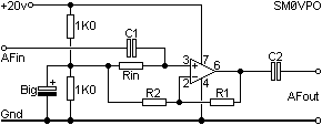
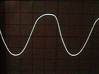
The AF amplifiers discussed so-far have the input signal fed into the + input which means that the output signal is in the same phase as the input signal. But what if we want the signal to be inverted? Easy, change the original configuration to feed the input signal into the -ve input:
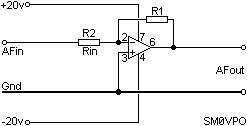
Another usefull point with this circuit, the output and inputs are 100% out of phase. The + input is referenced to 0v (ground) and so the -ve input MUST also be 0v. There will also be NO SIGNAL at the - input pin. This point in this circuit is called a "Virtual Earth".

Audio Power Amplifiers
Power = Volts X Amperes. So to get an AF power amplifier we must have both volts and current. We have already seen how to build a voltage amplifier, now let us give it a little current capability. We can do this by simply adding a pair of power transistors, one to give positive current, the other to give negative current.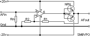
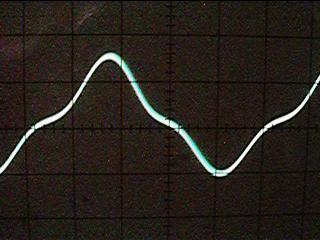
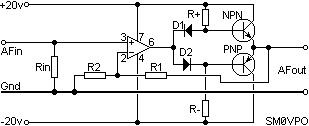

Audio Amplifier Limitations
Let us go back to our basic Op-Amp AF amplifier for a few moments, both the circuit and all the internal "gubbins": and
and 
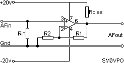
If you do not wish to muck about with transistors in conjunction with an Op-Amp then choose a "Power Op-Amp" such as the LM2020 which already has the power transistors built-in. This Op-Amp will provide 20 watts of audio. You can even use it to drive motors and lamps. This amplifier must be mounted on a heatsink.

Frequency Response
Now you know what an Op-Amp is all about and how it can be used to make amplifiers, let us consider the limitations of frequency response. I have already introduced the concept of "Unity Gain/Bandwidth" (UGB). So let us explore this a little more.Imagine for one moment that an Op-Amp had a Unity Gain/Bandwidth of 1000000Hz and we used resistors to set the amplifier voltage gain to 190 and then 20. What would the actual frequency response be? This graph shows you exactly what will happen.
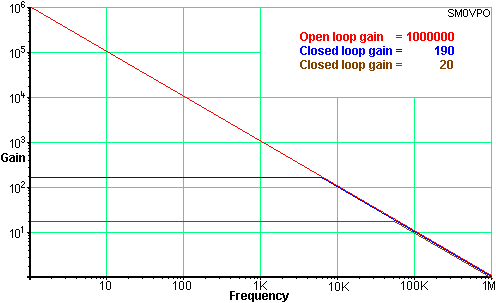
Frequency Response
But is UGB the end of the limitations story? No! Operational amplifiers have another property called "Slew Rate". This means that if the input waveform were to be a square-wave then the output would not change instantaneously. It would take a finite time for the output to change state.

In reality, the Slew rate characteristic of an Op-Amp will only affect signals of a very high frequency, or waveforms having a very steep rise and fall time, for example, square and sawtooth waveforms. For general audio work up to about 30KHz you can normally forget about this effect. The slew rate of an Op-Amp may complicate matters if you try to drive fast logic circuits, such as the 5400 and 7400 series. If you need to drive TTL circuits from Op-Amps then try to choose a logic gate that has a "Schmitt" input function. CMOS gates tend to be a bit more forgiving so you can usually get away with driving them directly from Op-Amps.

Active Low-Pass Filter
The high input impedance of the Op-Amp makes it especially usefull in filter design. Simple RC filters are good, but in order to take an output signal from them you need to load the filter. It is the load that "cocks up" everything. Your load circuit may be resistive, that will affect the responses of the filter. If your load is capacitive or inductive then you have little chance of predicting the outcome with any form of accuracy. So, let us consider the basic Low-Pass filter:

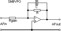
The Op-Amp really "earns it's corn" when you want a little more that 6dB/octave (20dB/decade) rolloff. You could simply cascade two single-pole filters, but inacuracies can enter when one filter is a load for the next. This filter is a 2-pole filter having a rolloff of 12dB/octave (40dB/decade), which in real terms is 25% of the original signal level:


Active High-Pass Filter
The active high-pass filter is almost the same as the low-pass, but the C and R are exchanged in the circuit to give the opposite response curve. First, the basic high-pass circuit element.


Active Band-Pass Filter
This is easy. Use a Low-Pass AND a High-Pass in cascade.
Active Rejection Filter
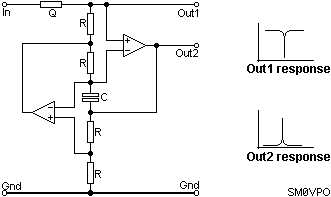
In many application you need to pass a complete band but with a filter to reject just one single frequency. There are many circuits for this, but here is one that I find so simple that even I understand it and I can remember the formula!

References
This is about all I wish to write on this subject. If you are interested in further reading then I suggest you take a trip to your local library. There are several educational Op-Amp books that you may find of interest:The ARRL Handbook For Radio Amateurs is rather good and easy to understand, but it is a little rudimentary. Assuming you know nothing, you assimilate all the Op-Amp section in one "sitting" on the toilet.
Electronic Circuits (Discrete and integrated) Donald L. Schilling & Charles Belove published by McGraw-Hill International is a real goldmine but tends to be a little "heavy" when it comes to mathematics - I keep my copy in the toilet so I am never short of reading material.
The IC OP-AMP Cookbook" is published by Sams & simply OP-AMPS published by Newnes press are both well worth reading. They contain a lot of useful information for all levels of knowledge. If you seriously wish to learn more, or have an Op-Amp reference data handy, then these are the books for you.
If you want an on-line resource for active filters then you could visit http://www.electronics-tutorials.com/filters/active-bandpass-filters.htm or http://www.filter-solutions.com/active.html where you will find loads of information, although a lot of it is designed to sell filter design software.

{ 0 comments... Views All / Send Comment! }
Post a Comment